Top Tips for Using USART UART Serial Port LCD Modules?
Using the USART/UART Serial Port LCD Module can greatly enhance your projects. These modules offer effective communication between microcontrollers and displays. Understanding how to use them properly can save time and frustration.
Connecting the USART/UART Serial Port LCD Module is often straightforward, but mistakes can happen. Make sure your baud rates match between devices. This simple step can prevent many communication issues. Also, be aware of the wiring; improper connections may lead to unexpected results.
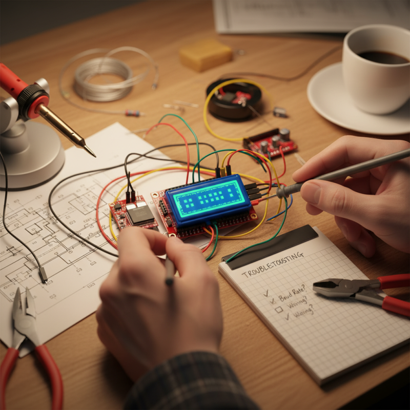
While the ease of use is appealing, don't overlook potential challenges. Debugging can be tedious when things go wrong. It's essential to have a systematic approach to troubleshooting. Consider creating a checklist to follow when issues arise. This will help streamline your process and boost your confidence. Embracing this tool opens doors to creative possibilities, but remember, every project has its learning curve.
Understanding USART and UART: Definitions and Differences
USART (Universal Synchronous/Asynchronous Receiver Transmitter) and UART (Universal Asynchronous Receiver Transmitter) are two fundamental communication protocols often used in embedded systems. The main difference lies in their modes of communication. USART can handle both synchronous and asynchronous modes, while UART operates only in asynchronous mode. This flexibility in USART allows for better synchronization across devices, but it also adds complexity that may not be needed for simpler applications.
According to a study by the Embedded Systems Association, nearly 70% of embedded systems utilize UART for basic communication needs. Its simplicity makes it a popular choice, especially in low-power applications. However, with this simplicity comes limitations. UART typically requires a matching baud rate, making it less versatile for complex systems that might involve multiple devices or varied communication speeds. This can lead to potential data loss if configurations are mismatched.
Additionally, the real-world implementation of these protocols often reveals challenges. For instance, when integrating a USART module, developers frequently encounter issues related to configuration mismatches. These can lead to debugging nightmares or even project delays. Such findings highlight the need for comprehensive testing and validation in any system design, especially for those venturing into mixed protocol environments. Understanding these nuances can significantly improve design efficiency and communication reliability in various applications.
Understanding USART vs UART: Key Features Comparison
This chart compares the key features of USART and UART, highlighting important parameters such as baud rate, data bits, parity, stop bits, and hardware flow control. USART typically supports higher baud rates and has more features compared to standard UART.
Essential Components of a Serial Port LCD Module
Serial port LCD modules are popular among electronic hobbyists. They provide a simple way to display information. Understanding their essential components ensures effective usage.
The core of these modules is often a microcontroller. This chip manages data transfer and displays it correctly. Additionally, a liquid crystal display is crucial. It translates electrical signals into visible information. Most modules include a backlight for better visibility. The contrast may vary, and finding the right settings is necessary.
Another component is the UART interface. It allows easy communication with various devices. However, users might face difficulties with configuration. Sometimes, connection issues arise. Using proper protocols can mitigate these challenges. Moreover, pay attention to the power supply. Insufficient power can lead to erratic behavior. Regular checks on wiring and soldering can prevent many common issues.
Steps to Connect LCD Modules Using USART UART
Connecting LCD modules using USART UART can seem daunting at first. However, by breaking it down into manageable steps, the process becomes much smoother. Start by gathering your components: an LCD module, a UART-to-USB converter, and connection wires. Get familiar with the pinouts of your LCD and ensure the power supply matches its requirements.
Once you have everything ready, begin by making connections. Connect the LCD's data pins to the corresponding pins on your UART module. Pay attention to the TX and RX lines; these are crucial for communication. It’s essential to ensure a stable connection, as loose wires can cause intermittent failures. Double-check your wiring; mistakes can lead to frustrating issues down the line.
After wiring, it’s time to configure your software. Set the USART UART parameters like baud rate and data bits according to the specifications of your LCD. A mismatch may prevent the display from showing any output. Test the setup with basic commands. If something doesn’t work, troubleshoot step by step. Sometimes, the simplest oversight, like forgetting to configure the baud rate properly, can lead to failures in communication.
Configuring Baud Rates and Communication Settings
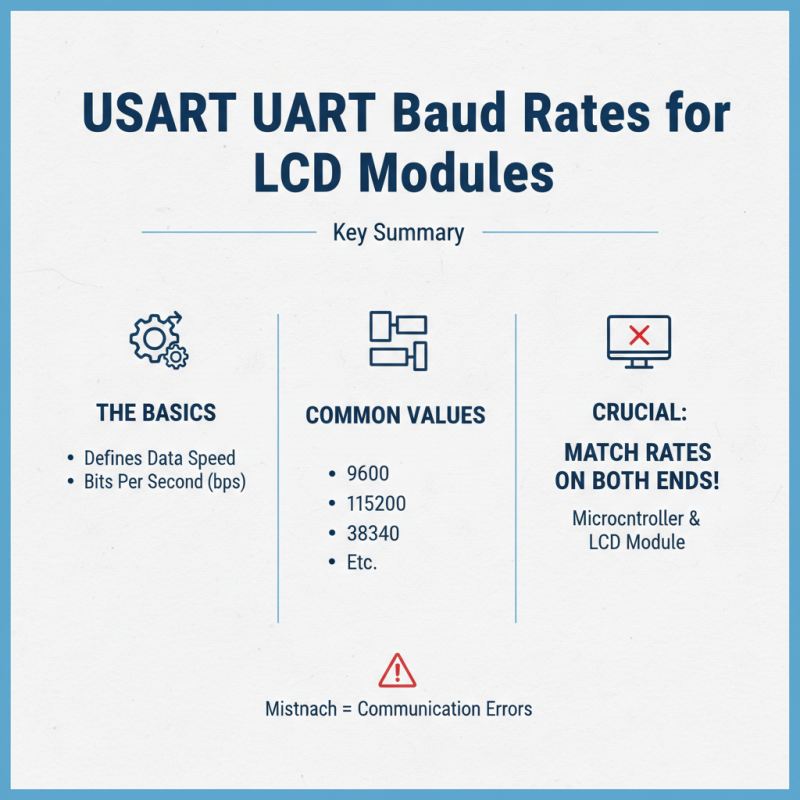
When configuring baud rates for USART UART serial port LCD modules, start with understanding the basics. Baud rate defines the speed of data transmission. Common values are 9600, 115200, and others. Choosing a mismatched baud rate can cause communication issues. Always match the baud rate on both ends of the connection—your microcontroller and LCD module.
Next, carefully set communication settings. This includes data bits, stop bits, and parity. For most applications, 8 data bits, 1 stop bit, and no parity work well. However, this might not fit all scenarios. Experimenting with these settings can sometimes lead to unexpected results. Occasionally, you may run into noise or miscommunication, especially in longer wires.
Finally, documentation plays a vital role. Always refer to the technical specifications of your LCD module. This helps avoid basic errors in setups. Each module can differ slightly in requirements, leading to frustration if not noted. A thorough understanding can save time and enhance performance. Don't overlook any detail, no matter how small—it can make a difference.
Common Troubleshooting Tips for Serial Port Connections
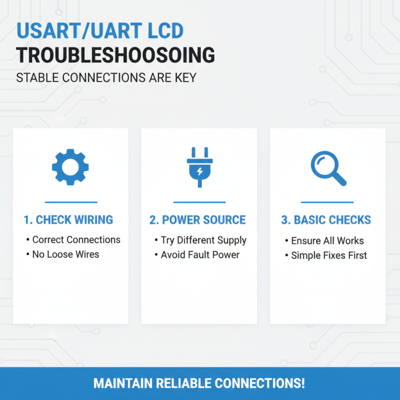
When working with USART UART serial port LCD modules, maintaining stable connections is key. If you encounter issues, start with basic checks. Ensure all wires are correctly connected. Loose connections can easily lead to errors. If you notice nothing works, try a different power source. Sometimes, it’s as simple as faulty power.
Another common pitfall is incorrectly set baud rates. Double-check the baud rate settings on both the LCD module and the serial device. A mismatch can cause garbled output or no display at all. Even a minor difference can create a headache. Adjusting these settings can often restore functionality quickly.
Watch out for unexpected interference. Nearby devices may disrupt signals. Shield your wiring when experimenting with multiple devices. Additionally, you might find that your microcontroller’s configuration is incorrect. This is easy to overlook and can lead to frustrating moments. Always verify that your programming aligns with your hardware setup. These steps can save time and help you troubleshoot effectively.